Fisher 3590 Valve Positioner Manual
The primary instruction manual for this series is typically found under historical Fisher documentation. Archival Access: You can view or download the manual on the Scribd Archive for Fisher 3590 Alternative Support:
: Maximum of 50 psi (3.4 bar). It should typically be 5 psig higher than the upper range limit of the input signal. Internal Resistance : 300 Ohms (for 3590ST). : Can be configured for Direct or Reverse action. Travel Range : Supports valve plug travel from 7/16 to 4 1/8 inches. Stewart Instrument Safety and Maintenance Qualified Personnel
) consists of electro-pneumatic valve positioners designed to accurately position a control valve stem in response to a DC input signal. This force-balance device is typically used with pneumatic actuators to provide high-precision flow control in industrial environments. Fisher 3590
Set the input signal to mid-range and verify the rotary shaft arm aligns with the case index marks.
The Fisher 3590 valve positioner manual provides detailed specifications, including:
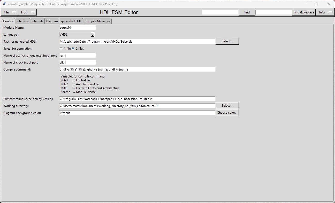
Here you can find links to several designs which I have created.
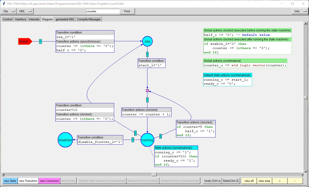
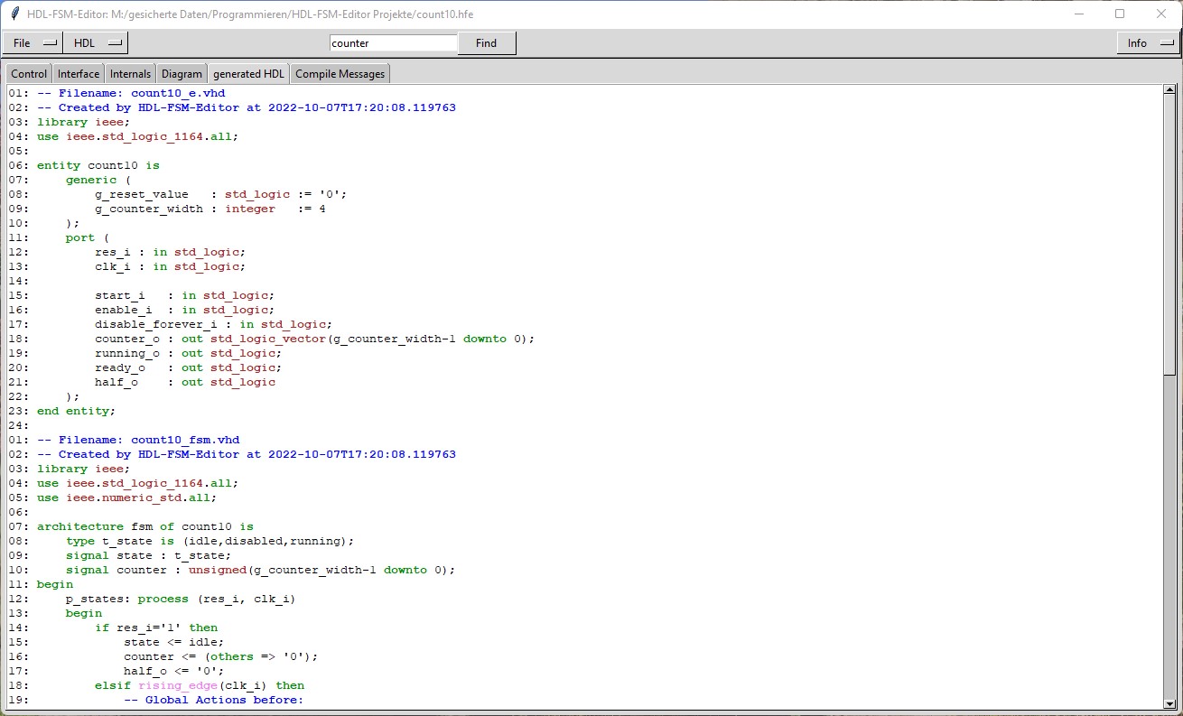
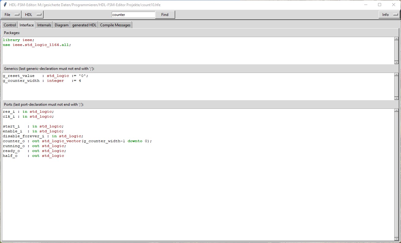
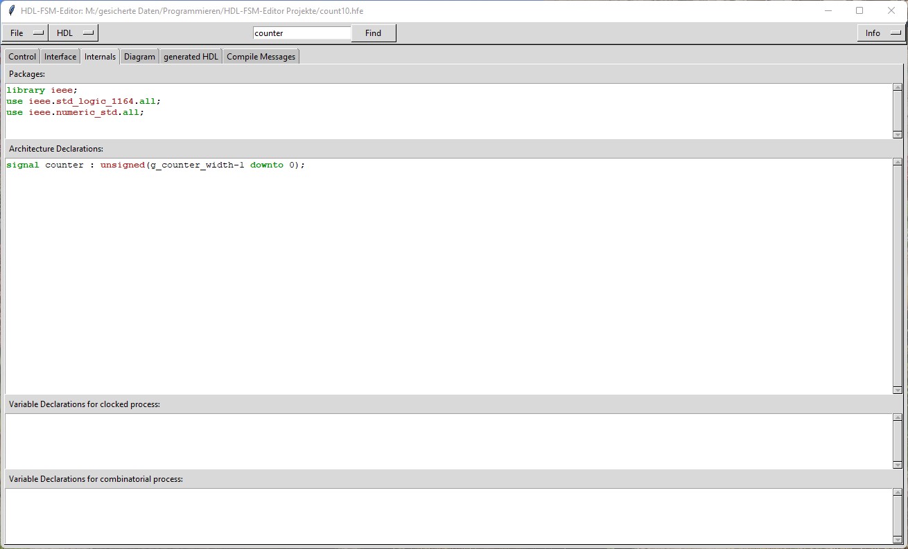
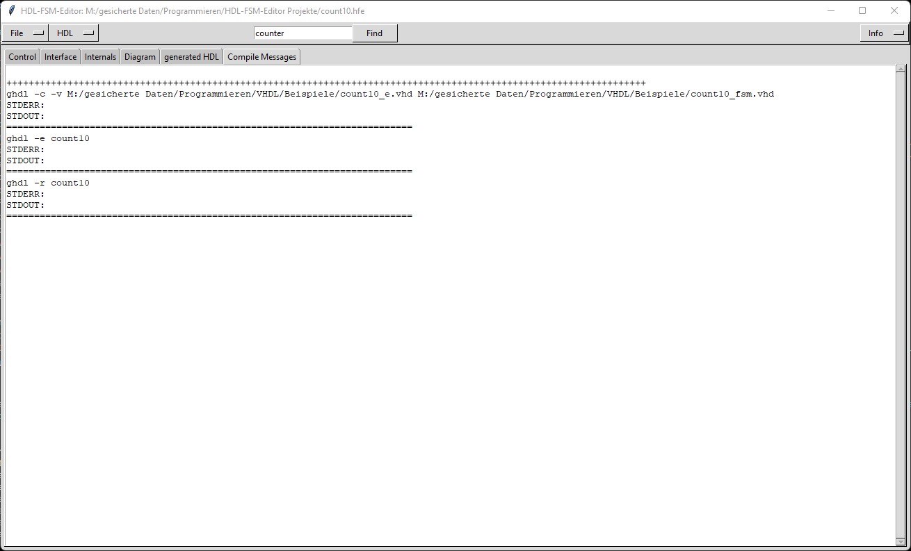
All designs are created by HDL-SCHEM-Editor and HDL-FSM-Editor and all designs are based at VHDL (only for division also Verilog is available).
By the link you will find all the needed source-files for both tools and also the generated VHDL/Verilog-files.
- Cordic module
- multiplication module
- multiplication module with carry-save adders (CS)
- multiplication module with signed digit adders (SD)
- multiplication module with binary stored-carry adders (BSC)
- multiplication module with Wallace tree (WT)
- multiplication module with Wallace tree and Booth encoding (WT_BOOTH)
- Karatsuba multiplication module
- division module
- division module at signed numbers
- SRT division module
- square module
- Cordic square-root module
- square-root module
- Uart
- Fifo
- clock-divider module
- AHB Multi-Layer Bus
- AHB to APB bridge
1. The Cordic module "rotate":
- The module "rotation" can rotate vectors by a given angle (Cordic rotation mode) or to the x-axis (Cordic vectoring mode).
- The module "rotation" can be configured by generics which define the number of bits of all the operands and which define the latency of the module (in clock cycles).
- The module "rotation" can be used to calculate the sine or cosine of an angle.
- The module "rotation" can be used to convert cartesian coordinates into polar coordinates and vice versa.
2. The multiplication module "multiply":
- The module "multiply" multiplies signed numbers.
- The module "multiply" can be configured by generics which define the number of bits of all the operands and which define the latency of the module (in clock cycles).
- The module "multiply" has an architecture "struct" which implements the classic written multiplication algorithm.
- The module "multiply" has an architecture "fpga" which uses the VHDL multiplication operator.
3. The multiplication module "multiply_cs":
- The module "multiply_cs" uses "carry-save" adders for a carry propagation not to the next bit but to the next addition.
- The module "multiply_cs" multiplies signed numbers.
- The module "multiply_cs" can be configured by generics which define the number of bits of all the operands and which define the latency of the module (in clock cycles).
4. The multiplication module "multiply_sd":
- The module "multiply_sd" uses "signed digit" adders for a carry propagation only to the next digit.
- The module "multiply_sd" multiplies signed numbers (internally coded with a redundant number system with radix 4).
- The module "multiply_sd" can be configured by generics which define the number of bits of all the operands and which define the latency of the module (in clock cycles).
5. The multiplication module "multiply_bsc":
- The module "multiply_bsc" uses "binary stored-carry" adders for a fast limited carry propagation.
- The module "multiply_bsc" multiplies signed numbers.
- The module "multiply_bsc" can be configured by generics which define the number of bits of all the operands and which define the latency of the module (in clock cycles).
6. The multiplication module "multiply_wt":
- The module "multiply_wt" uses a Wallace tree for a very fast product calculation.
- The module "multiply_wt" multiplies signed numbers.
- The module "multiply_wt" can be configured by generics which define the number of bits of all the operands and which define the latency of the module (in clock cycles).
- The module "multiply_wt_booth" uses Booth encoding with radix-4 conversion to reduce the number of partial products.
- The module "multiply_wt_booth" uses a Wallace tree for a very fast product calculation.
- The module "multiply_wt_booth" multiplies signed numbers.
- The module "multiply_wt_booth" can be configured by generics which define the number of bits of all the operands and which define the latency of the module (in clock cycles).
8. The Karatsuba multiplication module "multiply_karatsuba":
- The module "multiply_karatsuba" multiplies signed numbers.
- The module "multiply_karatsuba" can be configured by generics which define the number of bits of all the operands.
- The module "multiply_karatsuba" has an architecture "struct" which implements the Karatsuba multiplication algorithm.
- The module "multiply_karatsuba" has an architecture "mul_operator" which uses the VHDL multiplication operator.
9. The non restoring division module "division":
- The module "division" calculates quotient and remainder from signed dividend and signed divisor.
- The signs are removed before an unsigned division is executed and added afterwards.
- The module "division" is available as VHDL and as Verilog design.
- The module "division" can be configured by generics which define the number of bits of all the operands and which define the latency of the module (in clock cycles).
- The module "division" uses a non restoring division algorithm.
10. The non restoring division module "division_signed":
- The module "division_signed" calculates quotient and remainder from signed dividend and signed divisor.
- In contrary to the module division the signs are not removed before the division is executed.
- This leads to a quotient which is not coded as binary number with the bit weights 0 or 1,
but as a number with bit weights +1 or -1. After the division this number is converted into a binary number.
- After the conversion the quotient and the remainder are fixed in some cases.
- The module "division_signed" can be configured by generics which define the number of bits of all the operands and which define the latency of the module (in clock cycles).
- The module "division_signed" uses a non restoring division algorithm.
- The module "division_srt_radix2" calculates quotient and remainder from signed dividend and signed divisor.
- The module uses the SRT algorithm to make fast divisions possible even at operands which have a large number of bits.
- As a radix2 SRT algorithm is used the quotient is first not coded as binary number with the bit weights 0 or 1,
but as a number with bit weights -1, 0 or +1. After the division this number is converted into a binary number.
- The module "division_srt_radix2" can be configured by generics which define the number of bits of all the operands and which define the latency of the module (in clock cycles).
12. The square module "square":
- The module "square" calculates the square from a signed operand.
- The module is faster and smaller than the multiply module.
- The module "square" can be configured by generics which define the number of bits of the operand and which define the latency of the module (in clock cycles).
13. The Cordic square-root module "cordic_square_root":
- The module "cordic_square_root" calculates the root from an unsigned radicand by using the Hyperbolic Cordic algorithm.
- The module "cordic_square_root" determines not only the integer bits of the root, but also the same number of bits after the binary point.
- The module "cordic_square_root" can be configured by generics which define the number of bits of the operand and which define the latency of the module (in clock cycles).
14. The square-root module "square_root":
- The module "square_root" calculates the root from an unsigned radicand by an exact algorithm.
- When no root bits after the binary point are needed, then the module "square_root" needs the same number of iterations as the module "cordic_square_root".
Otherwise the module requires twice the number of iterations and also approximately twice as many resources.
- The module "square_root" can be configured by generics which define the number of bits of the operand and which define the latency of the module (in clock cycles).
15. The Uart module "uart":
- The module "uart" transfers data by the universal asynchronous receiver/transmitter protocol.
- The module "uart" uses a clock divider which can divide by non integer numbers.
- The module "uart" can be configured by generics which define the number of bits of the data and other behaviour of the module.
16. The Fifo module "fifo":
- The module "fifo" stores data according to the "first-in, first-out" principle.
- The module "fifo" can be configured by generics which define the number of bits of the data and the depth of the Fifo.
17. The clock-divider module "clock_divider":
- The module "clock_divider" creates a new clock with an integer or a non-integer multiple of the incoming clock period.
- The module "clock_divider" can be configured by generics which define the number of bits of the configuration inputs.
18. The AHB Multi-Layer Bus module "ahb_multilayer":
- The module "ahb_multilayer" is a generic AHB Multi-Layer Bus which connects several AHB masters to several AHB slaves.
- The module "ahb_multilayer" can be configured by generics which define the number of masters and slaves and some other properties.
19. The AHB to APB bridge module "ahb_apb_bridge":
- The module "ahb_apb_bridge" is a generic bridge module, which connects one AHB master to several APB slaves.
- The module "ahb_apb_bridge" can be configured by generics which define the number of APB slaves and some other properties.
The primary instruction manual for this series is typically found under historical Fisher documentation. Archival Access: You can view or download the manual on the Scribd Archive for Fisher 3590 Alternative Support:
: Maximum of 50 psi (3.4 bar). It should typically be 5 psig higher than the upper range limit of the input signal. Internal Resistance : 300 Ohms (for 3590ST). : Can be configured for Direct or Reverse action. Travel Range : Supports valve plug travel from 7/16 to 4 1/8 inches. Stewart Instrument Safety and Maintenance Qualified Personnel
) consists of electro-pneumatic valve positioners designed to accurately position a control valve stem in response to a DC input signal. This force-balance device is typically used with pneumatic actuators to provide high-precision flow control in industrial environments. Fisher 3590
Set the input signal to mid-range and verify the rotary shaft arm aligns with the case index marks.
The Fisher 3590 valve positioner manual provides detailed specifications, including: